L2TP Server and Client Configuration on Donyx Routers
L2TP (Layer 2 Tunneling Protocol) is a tunneling protocol utilized for establishing Virtual Private Networks (VPN) by encapsulating data packets. As the protocol does not provide native encryption, it is typically implemented in conjunction with IPsec for enhanced security.
Donyx routers feature both integrated L2TP Server and L2TP Client capabilities.
Objective:
To interconnect two local networks via the L2TP protocol.
| Configuration of dnxOS can be performed via the web interface or the CLI using SSH. The configuration logic remains consistent across both methods. |
Network integration via an L2TP tunnel
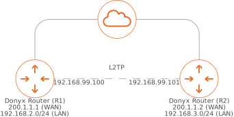
In this scenario, router R1 acts as the L2TP Server, with the local network 192.168.2.0/24 and public IP address 200.1.1.1. Router R2 acts as the L2TP Client, with the local network 192.168.3.0/24 and public IP address 200.1.1.2.
Configuration on Router R1 (Server)
The initial stage of server configuration involves creating user accounts for connecting clients.
-
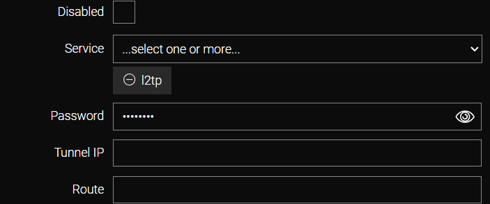
The following procedure is performed in the /service/client section:
-
Click Add and specify the username.
-
In the Service dropdown list, select the service for which the account is being created (in this example, l2tp).
-
Specify the account password in the Password field.
-
Click Apply to save the settings.
-
-
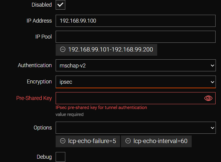
Subsequently, navigate to the /service/l2tp-server section. Complete the form as shown in the example.
Field |
Value |
IP Address |
The IP address assigned to the server’s tunnel interface (default: 192.168.99.100). |
IP Pool |
The range of IP addresses assigned to the L2TP server clients. |
Authentication |
Authentication protocol (default: mschap-v2). |
Encryption |
Virtual tunnel encryption protocol: mppe, ipsec, or none. |
Pre-Shared Key |
The shared key for IPsec. This field is available only if Encryption is set to ipsec. |
Options |
Additional configuration options. |
Debug |
Enables debug information in the system logs. This should be enabled only upon request from technical support. |
| To configure router R1 (Server) with IPsec, select the ipsec option in the Encryption field and specify the shared key in the Pre-Shared Key field. |
Configuration for Router R2 (Client) with IPSec
-
Navigate to the /tunnel/l2tp section, click Add, and assign a name to the new connection.

-
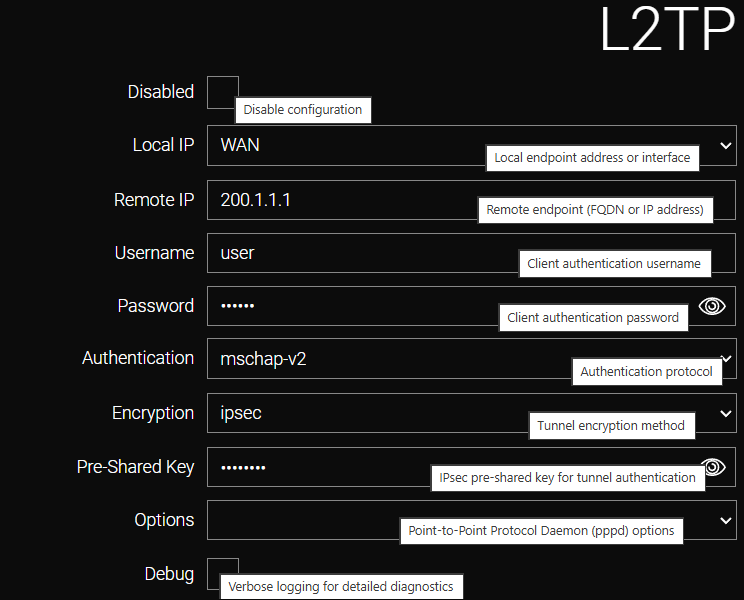
Complete the form as shown in the example.
Field |
Value |
Local IP |
The interface from which the tunnel is established. In this scenario, WAN (selected from the list). |
Remote IP |
The public IP address of the remote tunnel endpoint. In this scenario, 200.1.1.1 (public IP address of the server). |
Username |
The username for the L2TP client. In this scenario, user (must match the client name created on the server). |
Password |
The password for the L2TP client (the password assigned to the client on the server). |
Authentication |
Authentication protocol (default: any). |
Encryption |
Virtual tunnel encryption protocol: mppe, ipsec, or none. In this scenario, ipsec. |
Pre-Shared Key |
The shared key for IPsec. The secret key, must match the server configuration. This field is available only if Encryption is set to ipsec. |
Options |
Additional configuration options. |
Firewall Configuration
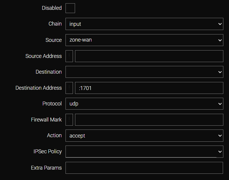
| When IPsec encryption is utilized, the router automatically implements pre-installed firewall rules to facilitate the establishment of L2TP tunnels. However, if encryption is not used, a rule permitting L2TP protocol traffic (UDP port 1701) must be manually created in the /firewall/filter section. This rule must be positioned above any rules that deny traffic from the WAN zone. |
-
To create the rule, navigate to the /firewall/filter section and complete the required fields.
-
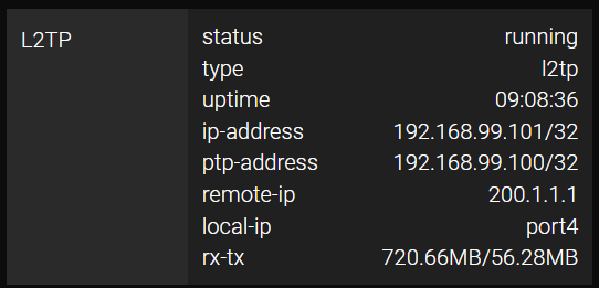
In the firewall table, move the newly created rule above any rules that deny traffic from the WAN zone.
Routing Configuration
The next step is to configure routing.
Routing Settings for R1 (Server)
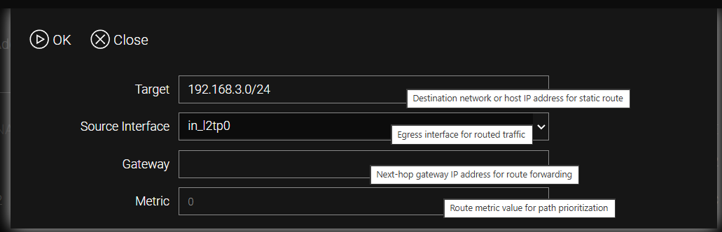
In the /ip/route/list section, click Add and define the routing parameters:
-
In the Target field, specify the destination subnet (in this example, 192.168.3.0/24).
-
In the Source Interface field, manually enter the interface name: in_l2tp0.
-
In the Gateway field, specify the gateway for the L2TP protocol (optional).
-
Click OK, then click Apply.
CLI Configuration (Server)
/ip route list add dst-addr=192.168.3.0/24 interface=in_l2tp0
    disabled -
    gateway -
    metric -
    src-addr -
    table main
    type unicast

  /ip route list apply
Routing Settings for R2 (Client)
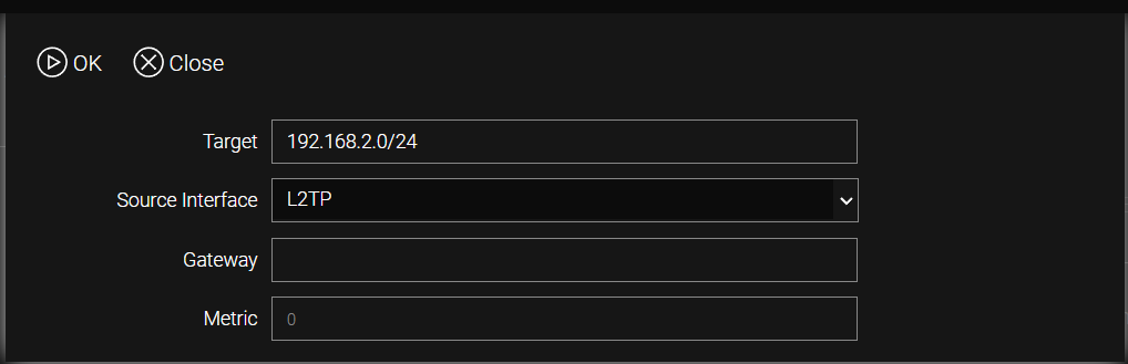
In the /ip/route/list section, click Add and define the routing parameters.
-
In the Target field, specify the destination subnet (in this example, 192.168.2.0/24).
-
In the Source Interface field, select the tunnel interface name (in this example, L2TP).
-
In the Gateway field, specify the gateway for the L2TP protocol (optional).
-
Click OK, then click Apply.
Ping (/tools/ping)
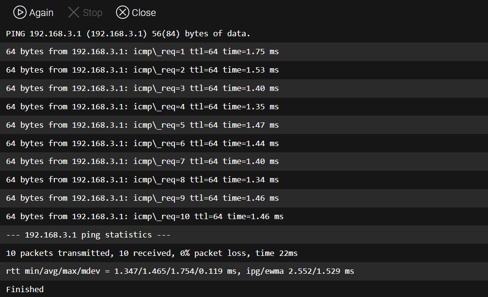
Verify connectivity using the Ping utility in the /tools/ping section. Perform a ping from the R1 server to the R2 client.
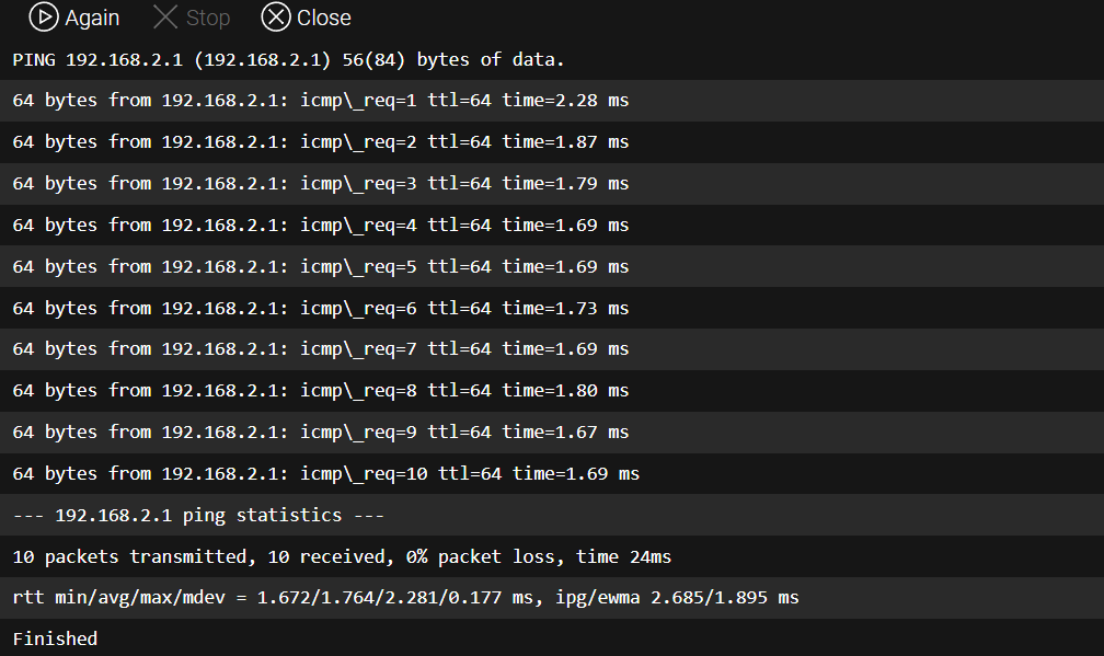
Verify the connection from the opposite side. Perform a ping from the R2 client to the R1 server.
| All modifications are permanently saved to the router configuration only after executing the /system config commit command or clicking the commit button in the web interface. |