EoIP Tunnel Configuration on Donyx Routers
The Ethernet over IP (EoIP) tunnel is a tunneling protocol developed by MikroTik. It operates at the Data Link Layer (L2) of the OSI model over IP (Layer 3) and creates a virtual bridge between two devices, providing a transparent Layer 2 connection.
Ethernet frames are encapsulated and transmitted through the tunnel as if the routers were directly connected, using Generic Routing Encapsulation (GRE) as the transport protocol.
The establishment of EoIP tunnels requires both endpoints to reside on the same network or have public IP addresses with no Network Address Translation (NAT) between them.
By default, EoIP tunnels do not include encryption. However, security can be implemented using IPsec.
Donyx routers support automatic IPsec configuration for EoIP tunnels. Note that full mutual compatibility is guaranteed only between Donyx devices; interoperability with third-party equipment may require manual adjustment.
L2-over-L3 tunneling should be implemented only when necessary, specifically in scenarios where requirements cannot be met through standard routing within L3 tunnels.
Example of equipment integration into a single L2 segment over the Internet:
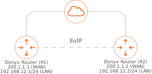
In this example, both routers are assigned public IP addresses (200.1.1.1 and 200.1.1.2), over which the tunnel is established. The local networks on both routers reside within the same subnet. These networks are integrated into a single segment through the L2 connectivity provided by the EoIP tunnel.
IPsec encryption is utilized for security.
The DHCP server must be disabled on all interfaces designated for integration into the single segment.
Configuration
In this scenario, the tunnel interfaces are named EOIP, and the WAN interfaces are named WAN.
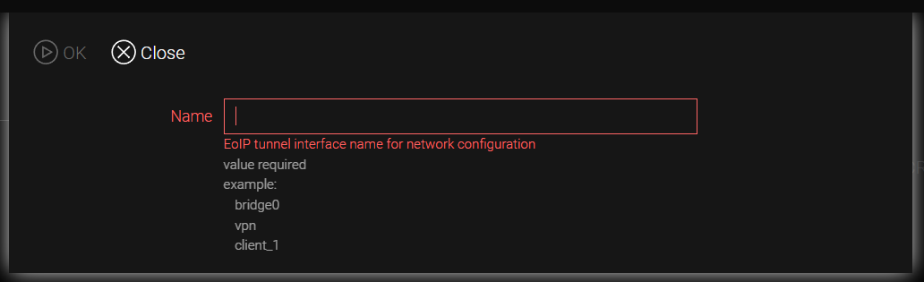
To establish the tunnel, the following steps are performed in the /tunnel/eoip section:
-
Click the Add button.
-
Assign a name to the new tunnel (e.g., EOIP).
-
In the Local IP field, select the interface through which the tunnel traffic will be transmitted.
-
In the Remote IP field, specify the public IP address of the remote endpoint.
-
In the Tunnel ID field, enter a unique identifier (e.g., 1000). This value must match on both routers.
-
If the Encryption field is set to ipsec, a pre-shared key must be specified in the psk field. This key must be identical on both routers.
-
Click Apply.
If IPsec encryption is enabled, corresponding tunnel entries are automatically generated in the /tunnel/ipsec section.
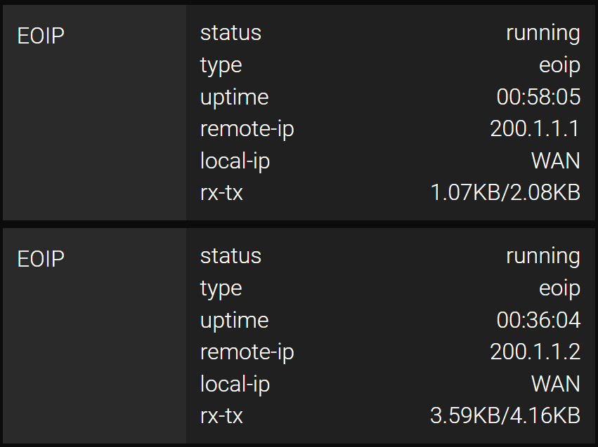
Tunnel statuses are displayed on the router’s dashboard:
Configuration on Router R1
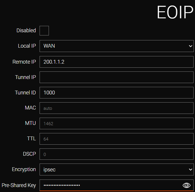
Field |
Value |
Local IP |
WAN (selected from the list). |
Remote IP |
200.1.1.2 (specified by the user). |
Tunnel ID |
1000 (specified by the user). |
Encryption |
none or ipsec (if ipsec is selected, necessary IPsec encryption settings will be automatically generated; identical settings must be configured on the other Donyx router). |
CLI Configuration (with IPsec Encryption)
To configure the tunnel via the CLI, establish an SSH session using administrator credentials and execute the following commands:
/tunnel eoip add name=EOIP
    disabled -
    dscp 0
    encryption ipsec
    local-ip WAN
    macaddr auto
    mtu 1462
    psk password
    remote-ip 200.1.1.2
    ttl 64
    tunnel-id 1000
    tunnel-ip -
    apply
Configuration on Router R2
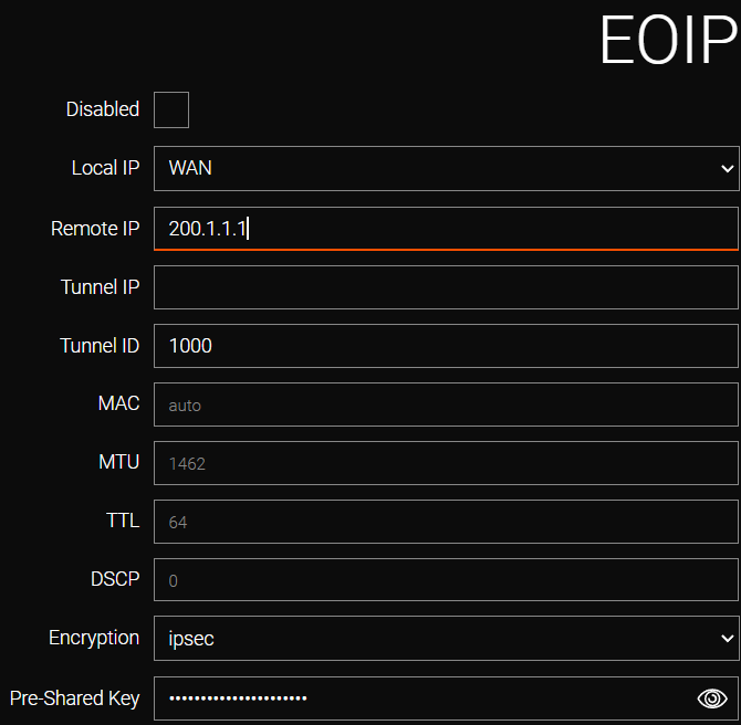
Field |
Value |
Local IP |
WAN (selected from the list). |
Remote IP |
200.1.1.1 (specified by the user). |
Tunnel ID |
1000 (specified by the user). |
Encryption |
none or ipsec (if ipsec is selected, necessary IPsec encryption settings will be automatically generated; identical settings must be configured on the other Donyx router). |
Local Network Connectivity
To facilitate communication between local networks, the virtual tunnel interfaces must be added to the corresponding bridges.
The following procedure is performed in the network/bridge section:
-
Select the bridge interface responsible for the local network segment (e.g., bridge0).
-
Add the tunnel interface (e.g., EOIP) to the Untagged ports list.
-
Click Apply.
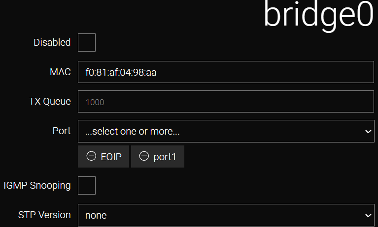
CLI Configuration
-
Use the /ip interface status command to display the list of existing bridges and their parameters.
-
Identify the bridge interface assigned the required IP address and subnet (e.g., 192.168.12.1/24). In this example, the target is bridge0.
/ip interface status -
Navigate to the bridge configuration section /network bridge bridge0
-
View the current ports within the bridge using the port command.
-
Add the tunnel interface to the port list. To maintain existing connectivity, the tunnel interface is added to the current list (e.g., port port1,EOIP, where EOIP is the name assigned to the tunnel).
-
Execute the apply command to confirm the bridge settings.
/network bridge bridge0 port EOIP
apply
An identical configuration procedure must be performed on the second router.
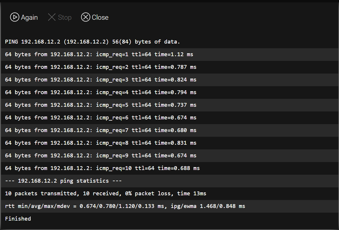
Ping (/tools/ping) — R2 from R1
Tunnel operation can be verified by sending a ping from the local address of router R1 to the address of the remote router R2.
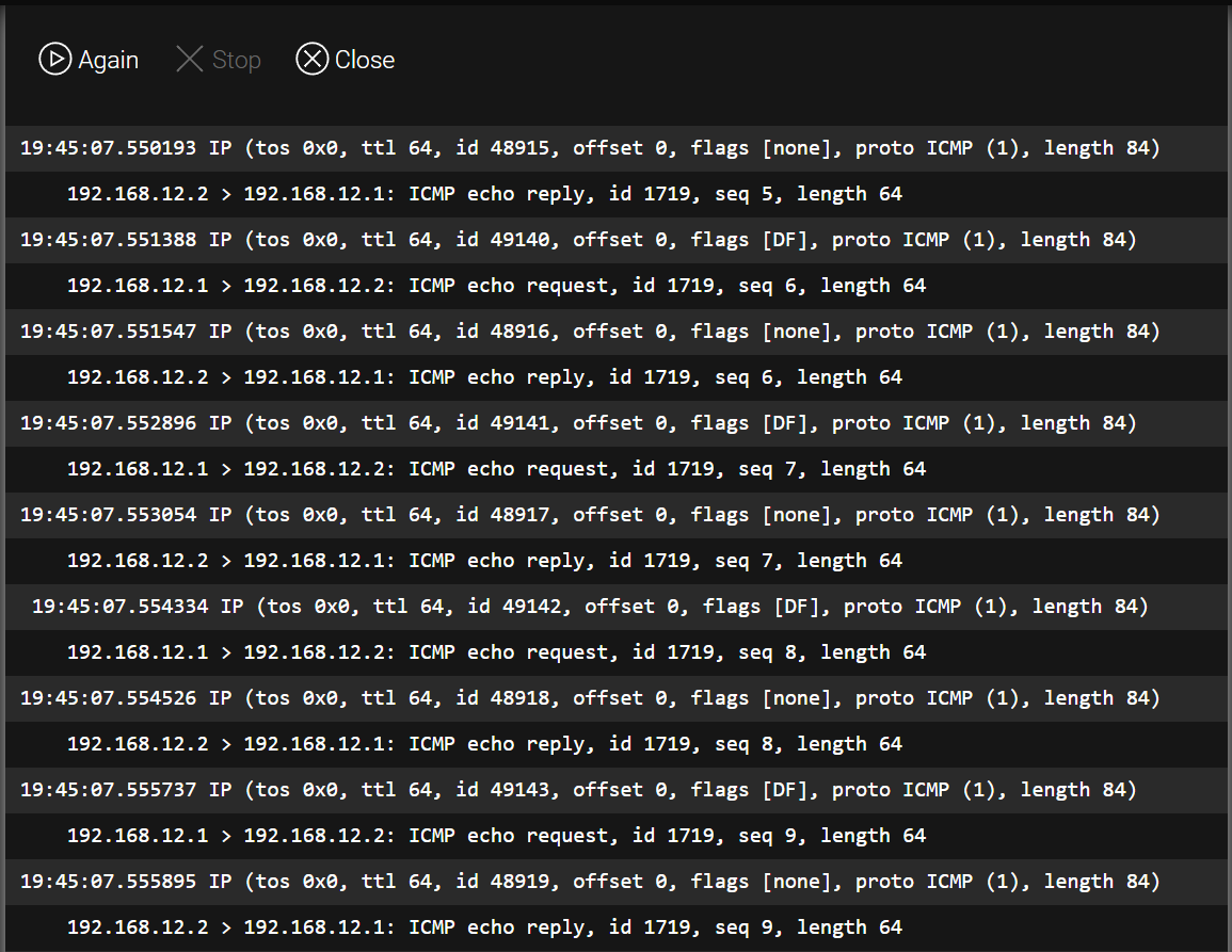
Tcpdump (/tools/sniffer) — R2
Use the sniffer to capture and analyze traffic passing through the interface.
Firewall Configuration
When IPsec encryption is utilized, the router automatically implements pre-installed firewall rules to facilitate the establishment of EOIP tunnels.
However, if encryption is not used, a specific rule permitting GRE protocol traffic must be manually created in the /firewall/filter section. This rule must be positioned above any rules that deny traffic from the WAN zone.
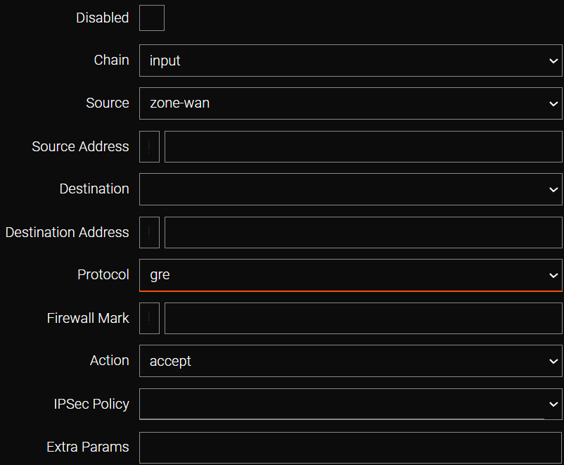
CLI Configuration
/firewall filter add chain=input
    action accept
    protocol gre
    src zone-wan
    reorder position=-1
    apply
/firewall filter status| All modifications are permanently saved to the router configuration only after executing the /system config commit command or clicking the commit button in the web interface. |