GRE Tunnel Configuration on Donyx Routers
A Generic Routing Encapsulation (GRE) tunnel establishes connectivity between two devices with mutually reachable IP addresses, enabling the configuration of routing via dedicated tunnel interfaces.
This type of tunnel does not include built-in encryption and is typically implemented within a private network or over an existing encrypted channel.
Donyx routers support automatic IPsec configuration for GRE tunnels. Please note that full mutual compatibility is guaranteed only between devices running the dnxOS platform; interoperability with third-party equipment may require manual adjustment.
Example of equipment integration via a GRE tunnel:
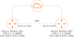
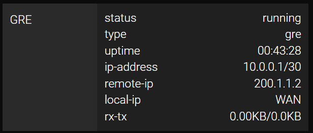
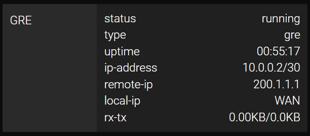
In this scenario, the routers access the Internet via interfaces with public IP addresses 200.1.1.1 and 200.1.1.2.
The GRE tunnel endpoints are assigned addresses 10.0.0.1 and 10.0.0.2 from the 10.0.0.0/30 subnet, providing the two necessary addresses for a point-to-point connection.
Configuration
The GRE tunnel is configured in the /tunnel/gre section of the dnxOS web interface or CLI.
To start the configuration, perform the following steps:
-
Click the Add button.
-
Assign a name to the tunnel (e.g., GRE).
| The interface cannot be named gre0 as this name is reserved for system requirements. |
-
In the Local IP field, select the interface through which the tunnel will operate.
-
In the Remote IP field, specify the public IP address of the remote endpoint.
-
In the Tunnel IP field, enter the IP address and subnet mask assigned to the virtual tunnel interface.
-
Specify a value in the Key field if multiple tunnels are being established between the same endpoints.
-
If encryption is required, select ipsec in the Encryption field and specify the pre-shared key in the psk field. Identical settings must be configured on the remote side.
-
Click Apply to save and activate the settings.
Configuration on Router R1
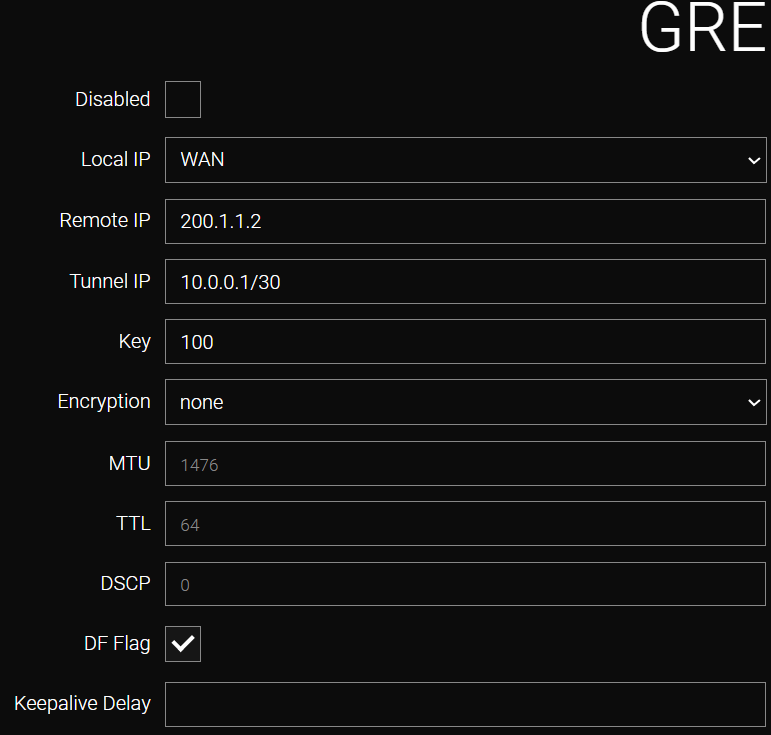
Field |
Value |
Local IP |
WAN (selected from the list). |
Remote IP |
200.1.1.2 (specified by the user). |
Tunnel IP |
10.0.0.1/30 (specified by the user). |
Key |
100 (specified by the user; optional if only a single GRE tunnel is present). |
Encryption |
none or ipsec (if ipsec is selected, necessary IPsec encryption settings will be automatically generated; identical settings must be configured on the other Donyx router). |
CLI Configuration
To configure the tunnel via the CLI, establish an SSH session using administrator credentials and execute the following commands:
/tunnel gre add name=GRE
    disabled -
    do-not-frag true
    dscp 0
    encryption none
    keepalive-delay -
    key 100
    local-ip WAN
    mtu 1476
    remote-ip 200.1.1.2
    ttl 64
    tunnel-ip 10.0.0.1/30
    apply
Configuration on Router R2
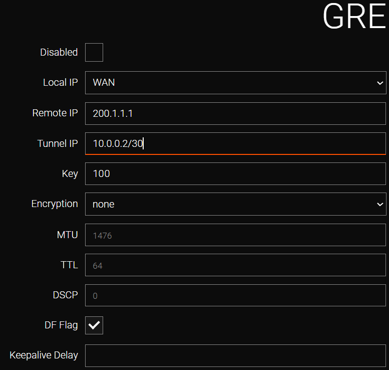
Field |
Value |
Local IP |
WAN (selected from the list). |
Remote IP |
200.1.1.1 (specified by the user). |
Tunnel IP |
10.0.0.2/30 (specified by the user). |
Key |
100 (specified by the user; optional if only a single GRE tunnel is present). |
Encryption |
none or ipsec (if ipsec is selected, necessary IPsec encryption settings will be automatically generated; identical settings must be configured on the other Donyx router). |
Firewall Configuration
When IPsec encryption is utilized, the router automatically implements pre-installed firewall rules to facilitate the establishment of GRE tunnels.
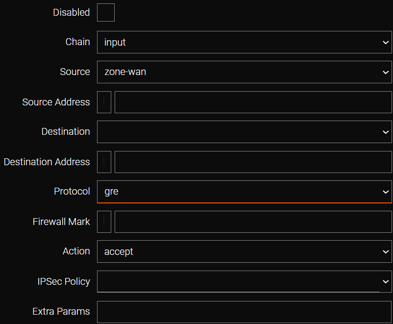
However, if encryption is not used, a specific rule permitting GRE protocol traffic must be manually created in the /firewall/filter section. This rule must be positioned above any rules that deny traffic from the WAN zone.
Static Route Configuration
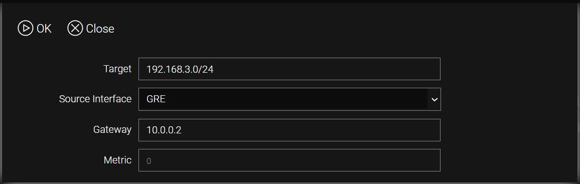
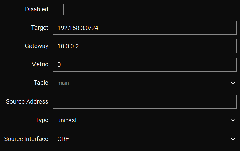
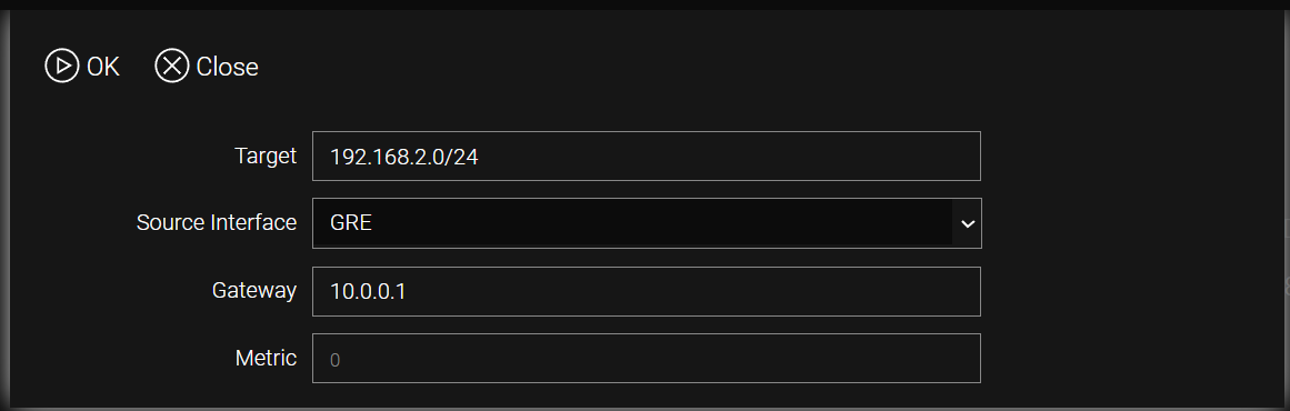
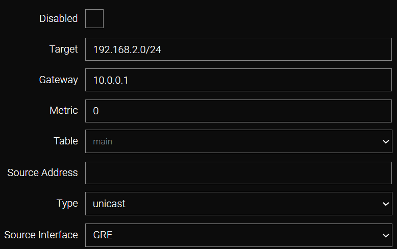
Static routes to the remote local networks are configured using the GRE interfaces and their respective tunnel IP addresses as gateways.
Static routing parameters are managed in the /ip/route/list section.
Ping (/tools/ping) — R2 from R1
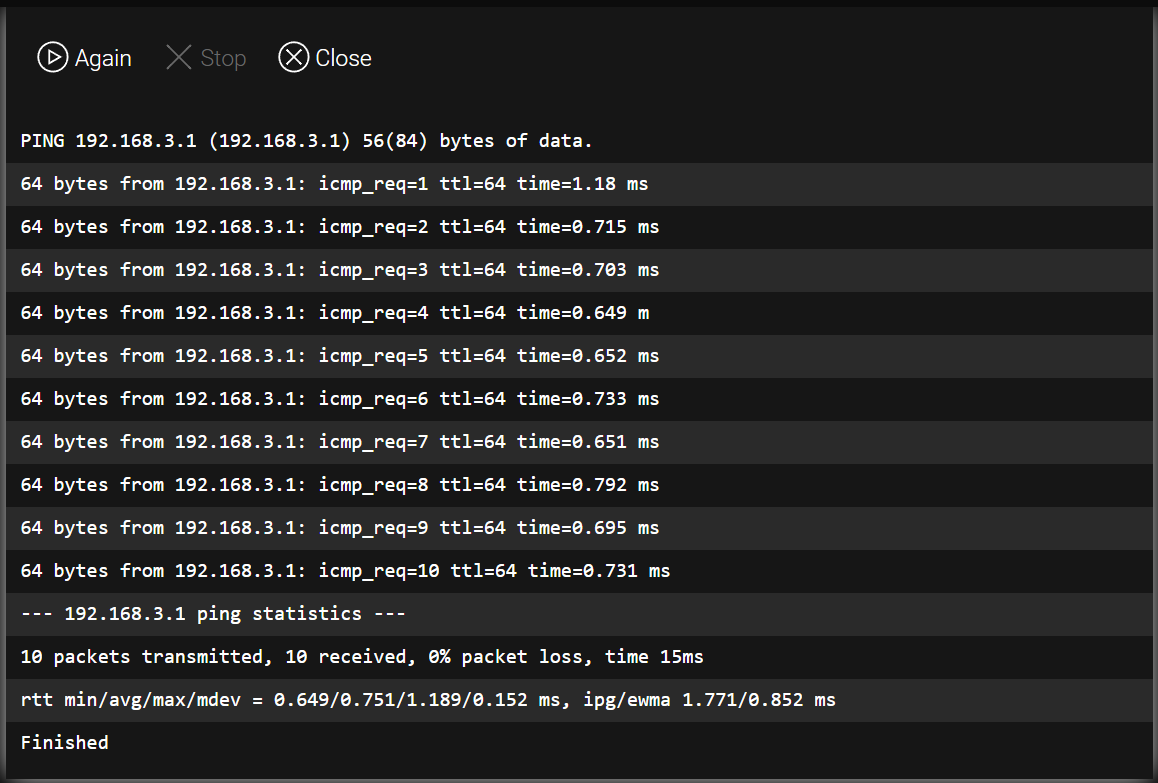
Tunnel operation can be verified by sending a ping from the local address of router R1 to the address of the remote router R2.
CLI Configuration
admin@Router[/]> /tools ping host=192.168.3.1
PING 192.168.3.1 (192.168.3.1) 56(84) bytes of data.
64 bytes from 192.168.3.1: icmp_req=1 ttl=64 time=1.18 ms
64 bytes from 192.168.3.1: icmp_req=2 ttl=64 time=0.715 ms
64 bytes from 192.168.3.1: icmp_req=3 ttl=64 time=0.703 ms
64 bytes from 192.168.3.1: icmp_req=4 ttl=64 time=0.649 ms
64 bytes from 192.168.3.1: icmp_req=5 ttl=64 time=0.652 ms
64 bytes from 192.168.3.1: icmp_req=6 ttl=64 time=0.733 ms
64 bytes from 192.168.3.1: icmp_req=7 ttl=64 time=0.651 ms
64 bytes from 192.168.3.1: icmp_req=8 ttl=64 time=0.792 ms
64 bytes from 192.168.3.1: icmp_req=9 ttl=64 time=0.695 ms
64 bytes from 192.168.3.1: icmp_req=10 ttl=64 time=0.731 ms

--- 192.168.3.1 ping statistics ---
10 packets transmitted, 10 received, 0% packet loss, time 15ms
rtt min/avg/max/mdev = 0.649/0.751/1.189/0.152 ms, ipg/ewma 1.771/0.852 ms| All modifications are permanently saved to the router configuration only after executing the /system config commit command or clicking the commit button in the web interface. |