VLAN Configuration on Donyx Routers
Objective:
To establish access to VLAN-based network segments on a Donyx router.
Network Topology for VLAN Configuration:
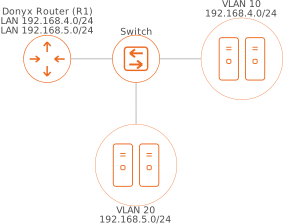
In this scenario, network clients are connected to a managed switch and isolated within two VLANs. Devices from the 192.168.4.0/24 subnet are assigned to VLAN 10, while those from the 192.168.5.0/24 subnet are assigned to VLAN 20.
The switch is connected to the router via a trunk link on physical port 4 of router R1. Necessary bridges and interfaces are already pre-configured; the objective is to establish tagged packet transmission via port 4.
Creating VLANs on R1
-
In the /network/device section, click Add.
-
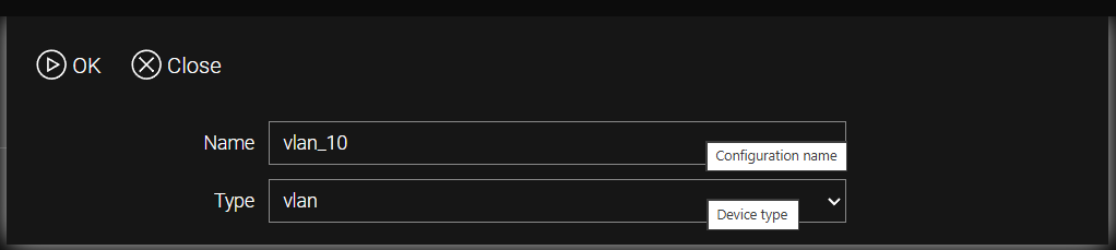
In the Name field, enter the identifier for the new device (e.g., vlan_10) and select vlan in the Type field.
-
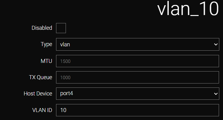
Complete the following parameters in the displayed menu.
Field |
Value |
Type |
Virtual device type (vlan). |
MTU |
Maximum transmission unit (1500 bytes by default). Modification is not recommended unless specifically required. |
TX Queue |
Maximum packet queue size. Modification is not recommended unless specifically required. |
Host Device |
The physical device on which the virtual VLAN subinterface is created. In this example, port4 is used for the connection to the switch. |
VLAN ID * |
The VLAN tag identifier, which must match across the entire VLAN domain. In this example, the VLAN ID is set to 10. |
| * Note that some lower-range identifiers are reserved for internal system use. |
-
Click Apply.
-
The configuration for the vlan_20 device is performed in a similar manner using port4 with VLAN ID 20.
Connecting Local Clients to VLAN Network Segments
The following procedure is performed to connect local clients to VLAN network segments:
Identify the IP subnets assigned to the bridge interfaces in the /ip/interface section. Then, add the corresponding VLAN interface to the specific bridge in the /network/bridge section.
Isolated VLAN Routing on the Router (Router-on-a-Stick)
In this configuration, client devices are connected to a managed switch, while the router performs traffic routing between distinct VLAN segments and their corresponding subnets.
The setup procedure involves the following requirements:
-
Virtual Device Creation: For each routed VLAN, a corresponding virtual device (subinterface) must be created in the /network/device section.
-
Interface Configuration: In the /ip/interface section, individual interfaces must be created for each virtual device, with appropriate IP addresses and subnet masks assigned.
-
Gateway Assignment: The IP address of the respective VLAN interface must be configured as the default gateway on all client devices within that VLAN.
-
DHCP Services: If the Donyx router acts as a DHCP server, address allocation for the corresponding subnets must be configured in the /service/dhcp/server section.
CLI Configuration
-
Example for VLAN ID 10, VLAN 20, and VLAN 30 with router IP addresses 192.168.4.1/24, 192.168.5.1/24, and 192.168.6.1/24 respectively. Port 4 is utilized as the tagged (trunk) port.
/network device add name=vlan_10 type=vlan
    device port4
    disabled -
    mtu 1500
    tx-queue-len 1000
    vid 10

/network device apply
/network device add name=vlan_20 type=vlan
device port4
disabled -
mtu 1500
tx-queue-len 1000
vid 20
/network device apply/network device add name=vlan_30 type=vlan
device port4
disabled -
mtu 1500
tx-queue-len 1000
vid 30
/network device apply/ip interface add device=vlan_10 type=static
disabled -
gateway -
ip-address -
ip-address 192.168.4.1/24
metric 200
/ip interface apply/ip interface add device=vlan_20 type=static
disabled -
gateway -
ip-address -
ip-address 192.168.5.1/24
metric 200
/ip interface apply/ip interface add device=vlan_30 type=static
disabled -
gateway -
ip-address -
ip-address 192.168.6.1/24
metric 200
/ip interface apply
/system config commit| In this configuration, the router provides unrestricted access between all VLAN networks terminated on the device. Provided the router serves as the default gateway for hosts within the segments separated by VLANs, all such segments will be mutually accessible. |
If access restrictions between VLAN networks are required, traffic filtering between logical interfaces must be configured in the /firewall/filter section.
| An IP address for an interface in the /ip/interface section associated with a VLAN device can only be configured if the physical host port has an active link. Otherwise, the interface remains in an error state until a link is established on the physical port. |
-
DHCP Configuration for VLAN Segments. The configuration of DHCP services for connected VLAN segments utilizes an address pool range from x.x.x.100 to x.x.x.200.
/service dhcp server add interface=vlan_10
    disabled -
    dns-server -
    flags -
    leasetime 12h
    mode server
    ntp-server -
    option -
    pool -
    pool 192.168.4.100-192.168.4.200
    router 192.168.4.1
/service dhcp server add interface=vlan_20
disabled -
dns-server -
flags -
leasetime 12h
mode server
ntp-server -
option -
pool -
pool 192.168.5.100-192.168.5.200
router 192.168.5.1/service dhcp server add interface=vlan_30
disabled -
dns-server -
flags -
leasetime 12h
mode server
ntp-server -
option -
pool -
pool 192.168.6.100-192.168.6.200
router 192.168.6.1
/service dhcp server apply
/system config commit| All modifications are permanently saved to the router configuration only after executing the /system config commit command or clicking the commit button in the web interface. |