Configuring GPIO on Donyx Routers
GPIO (General-Purpose Input/Output) interfaces allow Donyx routers to interact with external electrical circuits and devices. Depending on the selected operating mode, a GPIO pin can either monitor an external signal (input mode) or control external equipment (output mode).
Typical GPIO applications include:
-
monitoring sensors and switches;
-
controlling relays, indicators, or other external equipment;
-
generating events based on changes in the electrical state of an input.
The number of available GPIO pins and their electrical characteristics depend on the router model. Refer to the user manual for your router for hardware specifications and pin assignments.
| Before connecting external equipment to GPIO pins, ensure that the electrical characteristics of the connected circuit comply with the router specifications. |
Before You Begin
Observe the following safety requirements when working with GPIO:
-
Apply voltage to GPIO input pins only after the router has fully powered on.
-
The voltage applied to a GPIO input must never exceed the router supply voltage.
-
Failure to comply with these requirements may result in permanent hardware damage and void the manufacturer’s warranty.
|
Voltage compatibility and the use of a pull‑up/pull‑down resistor (e.g., 10 kΩ) are model‑specific. Some Donyx routers require the input voltage to strictly equal the supply voltage, while others allow a difference if a resistor is installed. These details vary by model and hardware revision. |
Before connecting any external circuit, always refer to the Using GPIO section in the User’s Guide for your specific router model. The guide provides the exact electrical ratings, pin assignments, and any model-specific requirements (such as resistor usage) that apply to your device.
Configure a GPIO
Open the GPIO configuration page peripheral→gpio. Select the GPIO you want to configure from the list.
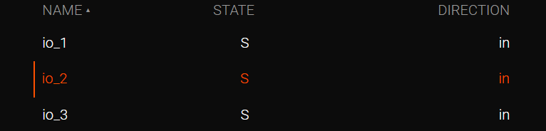
The available parameters depend on the selected operating mode.
Input Mode
To configure the GPIO as an input:
-
Set Direction to in.
-
Configure the Trigger mode.
-
Specify the Debounce interval if required.
-
Click Apply.
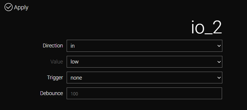
The following parameters are available in input mode:
Value |
Displays the current voltage level detected on the GPIO input. |
Trigger |
Specifies which signal transition generates an event. The router’s response to the event is configured separately in the Events section. |
Debounce |
Defines the debounce interval in milliseconds to suppress false triggering caused by switch bounce or electrical noise. |
The following trigger modes are available:
none |
No events are generated. |
rising |
Generates an event when the input changes from low to high. |
falling |
Generates an event when the input changes from high to low. |
both |
Generates an event on both signal transitions. |
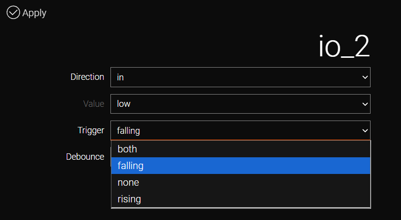
| Actions to be performed by the router when the event occurs are configured separately in the Events section. |
Output Mode
To configure the GPIO as an output:
-
Open the required GPIO.
-
Set Direction to out.
-
Select the required output level in the Value field.
-
Click Apply.
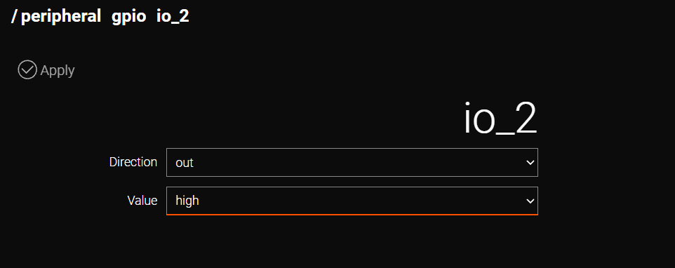
The following values are available:
high |
Applies a high voltage level to the GPIO output. |
low |
Applies a low voltage level to the GPIO output. |
GPIO Parameters
Direction |
Selects the GPIO operating mode (in or out). |
Value |
Displays the current input level or specifies the output level, depending on the selected operating mode. |
Trigger |
Defines which input signal transition generates an event. |
Debounce |
Specifies the debounce interval in milliseconds. |
Protectd
The Protectd service provides active electrical protection for GPIO pins.
It continuously monitors GPIO lines for electrical faults, such as short circuits or overcurrent conditions. If a fault is detected, the affected GPIO is automatically disabled to protect the router hardware.
Once the external fault has been eliminated, the service must be restarted manually from the Protectd page to restore GPIO operation.
| Restart the service only after the external wiring fault has been corrected. |
Example: Sending an SMS on a GPIO State Change
The following example demonstrates how GPIO can be used with the Events mechanism to perform an action when the GPIO input state changes.
In this example, the router sends an SMS message when the io_1 input changes from low to high.
The configuration consists of two steps:
-
Configure io_1 to generate a trigger when its state changes.
-
Create an event that sends an SMS when io_1 changes to high.
Configure the GPIO Trigger
-
Open the io_1 GPIO settings.
-
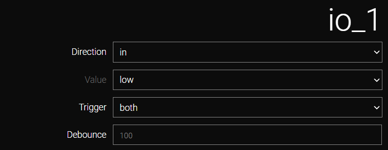
Set Direction to in.
-
Set Trigger to both.
-
Click Apply.
With both selected, GPIO events are generated when the input state changes in either direction: from low to high or from high to low.

Configure the Event
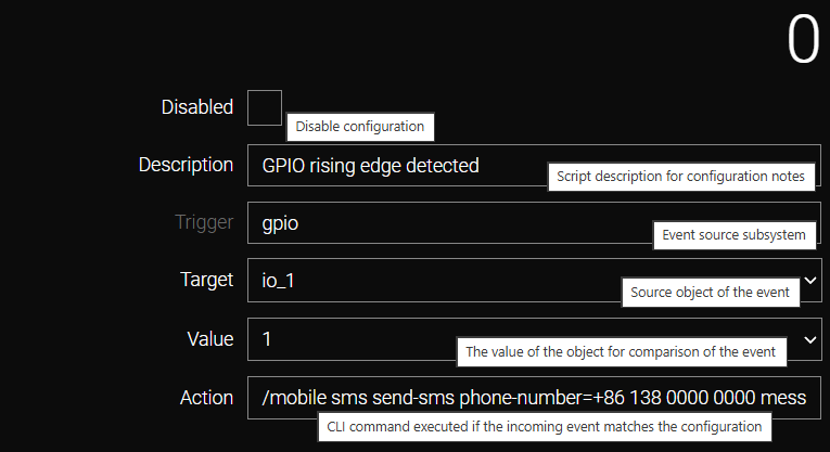
Configure the event as follows:
Parameter |
Value |
Disabled |
false |
Description |
GPIO rising edge detected |
Trigger |
gpio |
Target |
io_1 |
Value |
1 |
Action |
/mobile sms send-sms phone-number=+8613800000000 message="GPIO rising" |
In this configuration, io_1 is the event source and 1 corresponds to the high state. Therefore, although the GPIO Trigger parameter is set to both, this event is executed only when io_1 changes from low to high.
When the condition is met, the router executes the configured Action and sends the SMS message GPIO rising to the specified phone number.