L2TPv3 Tunnel Configuration on Donyx Routers
L2TPv3 (Layer 2 Tunneling Protocol version 3) is a tunneling protocol that encapsulates Data Link Layer (L2) traffic for transmission over IP networks.
Operating on a point-to-point basis, it supports two primary modes:
-
IP Protocol mode: Operates directly as IP protocol number 115. This mode is recommended when no NAT exists between the tunnel endpoints.
-
UDP mode: Operates over the UDP protocol, enabling the tunnel to traverse NAT boundaries.
As with many other tunneling protocols, L2TPv3 does not include built-in encryption. Consequently, it should be implemented within private networks or secured using additional encryption, such as IPsec.
| L2-over-L3 tunneling should be utilized only when necessary, specifically in scenarios where requirements cannot be met through standard routing within L3 tunnels. |
Integration of equipment into a single L2 segment via an L2TPv3 tunnel:
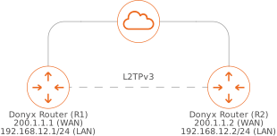
In this example, both routers are assigned public IP addresses, over which the tunnel is established. The local networks on both routers reside within the same subnet. These networks are integrated into a single L2 segment using the L2TPv3 tunnel. To prevent IP address conflicts, the DHCP server must be disabled on the local network interfaces designated for integration.
To establish the tunnel, the following steps are performed in the /tunnel/l2tpv3 section of the web interface or CLI:
-
Click the Add button.
-
Assign a name to the new tunnel.
-
Complete the configuration fields.
L2TPv3 Tunnel Configuration with UDP Encapsulation (without IPsec)
In this example, the tunnel interfaces are named L2TPv3, and the WAN interfaces are named WAN.
Tunnel statuses are displayed on the router’s dashboard:
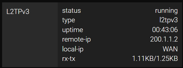
Configuration on Router R1
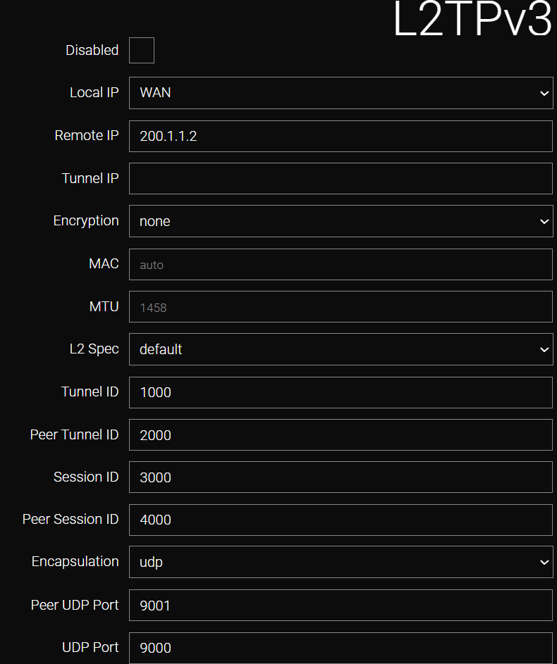
Field |
Value |
Local IP |
WAN (selected from the list). |
Remote IP |
200.1.1.2 (specified by the user). |
L2 Spec |
Default (selected from the list). |
Tunnel ID |
1000 (specified by the user). |
Peer Tunnel ID |
2000 (specified by the user). |
Session ID |
3000 (specified by the user). |
Peer Session ID |
4000 (specified by the user). |
Encapsulation |
UDP (selected from the list). |
Peer UDP Port |
9001 (specified by the user). |
UDP Port |
9000 (specified by the user). |
CLI Configuration on Router R1 (without IPsec Encryption)
To configure the tunnel via the CLI, establish an SSH session using administrator credentials and execute the following commands:
/tunnel l2tp-v3 add name=L2TPv3
    disabled false
    encap udp
    encryption none
    local-ip WAN
    l2spec-type default
    macaddr auto
    mtu 1458
    peer-session-id 4000
    peer-tunnel-id 2000
    remote-ip 200.1.1.2
    session-id 3000
    tunnel-id 1000
    tunnel-ip -
    udp-dport 9001
    udp-sport 9000
    apply
Configuration on Router R2
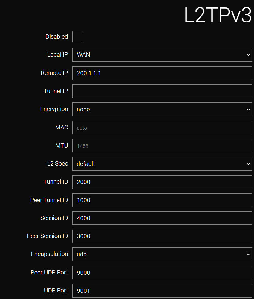
Field |
Value |
Local IP |
WAN (selected from the list). |
Remote IP |
200.1.1.1 (specified by the user). |
L2 Spec |
Default (selected from the list). |
Tunnel ID |
2000 (specified by the user). |
Peer Tunnel ID |
1000 (specified by the user). |
Session ID |
4000 (specified by the user). |
Peer Session ID |
3000 (specified by the user). |
Encapsulation |
UDP (selected from the list). |
Peer UDP Port |
9000 (specified by the user). |
UDP Port |
9001 (specified by the user). |
CLI Configuration on Router R2 (without IPsec Encryption)
/tunnel l2tp-v3 add name=L2TPv3
    disabled false
    encap udp
    encryption none
    local-ip WAN
    l2spec-type default
    macaddr auto
    mtu 1458
    peer-session-id 3000
    peer-tunnel-id 1000
    remote-ip 200.1.1.1
    session-id 4000
    tunnel-id 2000
    tunnel-ip -
    udp-dport 9000
    udp-sport 9001
    apply
Firewall Configuration
The firewall must be configured to permit incoming packets; this configuration is performed in the /firewall/filter section.
Configuration on Router R1
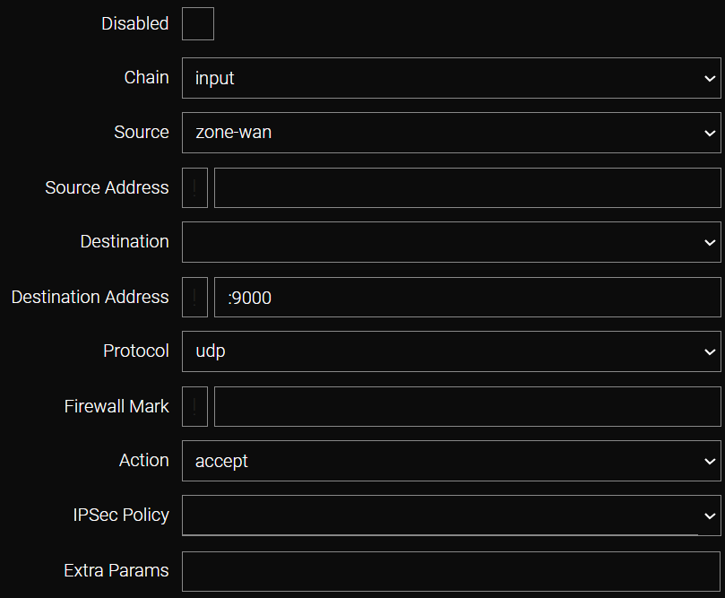
The port number must match the UDP Port value previously specified in the tunnel configuration.
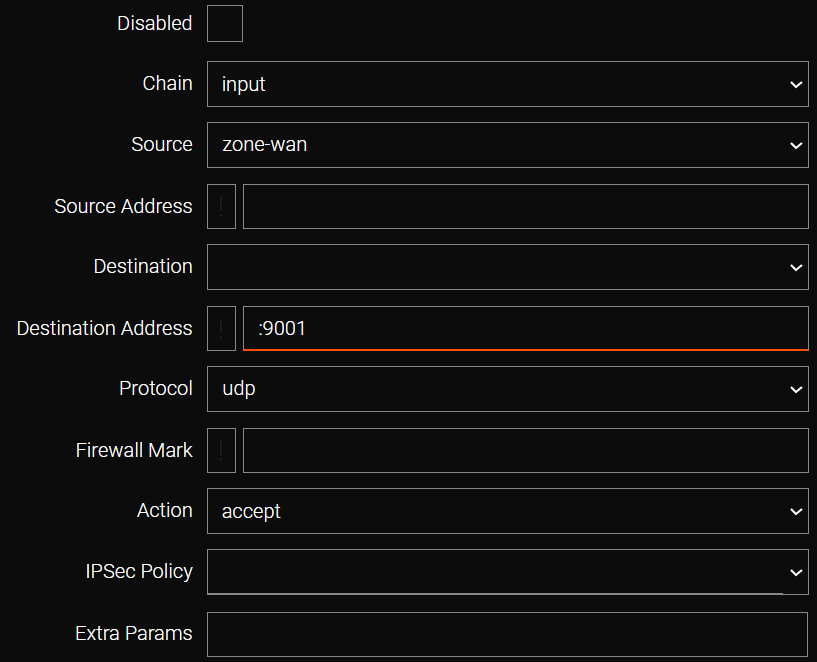
L2TPv3 Tunnel Configuration with UDP Encapsulation (with IPsec)
Configuration on Router R1
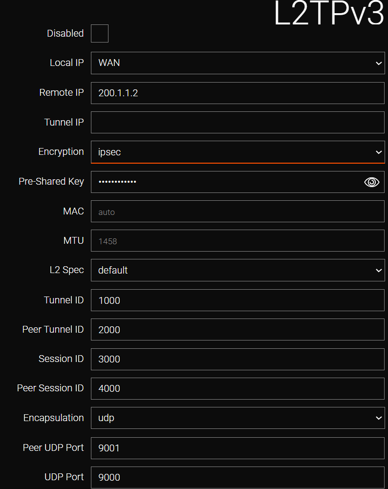
Field |
Value |
Local IP |
WAN (selected from the list). |
Remote IP |
200.1.1.2 (specified by the user). |
Encryption |
ipsec |
Pre-Shared Key |
Password |
L2 Spec |
Default (selected from the list). |
Tunnel ID |
1000 (specified by the user). |
Peer Tunnel ID |
2000 (specified by the user). |
Session ID |
3000 (specified by the user). |
Peer Session ID |
4000 (specified by the user). |
Encapsulation |
UDP (selected from the list). |
Peer UDP Port |
9001 (specified by the user). |
UDP Port |
9000 (specified by the user). |
CLI Configuration on Router R1 (with IPsec Encryption)
/tunnel l2tp-v3 add name=L2TPv3
    encap udp
    encryption ipsec
    local-ip bridge1
    l2spec-type default
    macaddr auto
    mtu 1458
    peer-session-id 4000
    peer-tunnel-id 2000
    psk password
    remote-ip 200.1.1.2
    session-id 3000
    tunnel-id 1000
    udp-dport 9001
    udp-sport 9000

  /tunnel l2tp-v3 apply
Configuration on Router R2
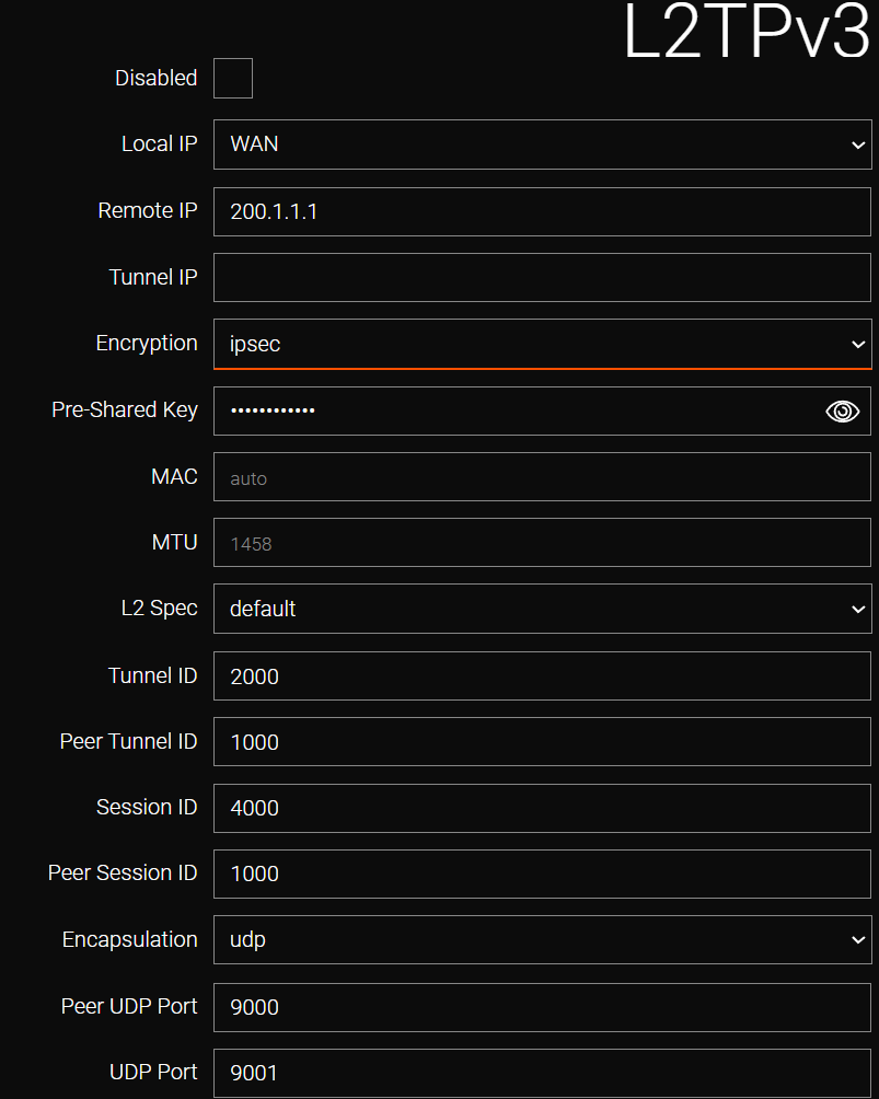
Field |
Value |
Local IP |
WAN (selected from the list). |
Remote IP |
200.1.1.1 (specified by the user). |
Encryption |
ipsec |
Pre-Shared Key |
Password |
L2 Spec |
Default (selected from the list). |
Tunnel ID |
2000 (specified by the user). |
Peer Tunnel ID |
1000 (specified by the user). |
Session ID |
4000 (specified by the user). |
Peer Session ID |
3000 (specified by the user). |
Encapsulation |
UDP (selected from the list). |
Peer UDP Port |
9000 (specified by the user). |
UDP Port |
9001 (specified by the user). |
CLI Configuration on Router R2 (with IPsec Encryption)
/tunnel l2tp-v3 add name=L2TPv3
    encap udp
    encryption ipsec
    local-ip bridge1
    l2spec-type default
    macaddr auto
    mtu 1458
    peer-session-id 3000
    peer-tunnel-id 1000
    psk password
    remote-ip 200.1.1.1
    session-id 4000
    tunnel-id 2000
    udp-dport 9000
    udp-sport 9001
/tunnel l2tp-v3 apply| If the tunnel is configured with IPsec encryption, additional firewall configuration is not required. |
Local Network Connectivity
To facilitate communication between local networks, the virtual tunnel interfaces must be added to the corresponding bridges.
The following procedure is performed in the network/bridge section:
-
Select the bridge interface responsible for the local network segment (e.g., bridge0).
-
Add the tunnel interface (e.g., L2TPv3) to the Untagged ports list.
-
Click Apply.
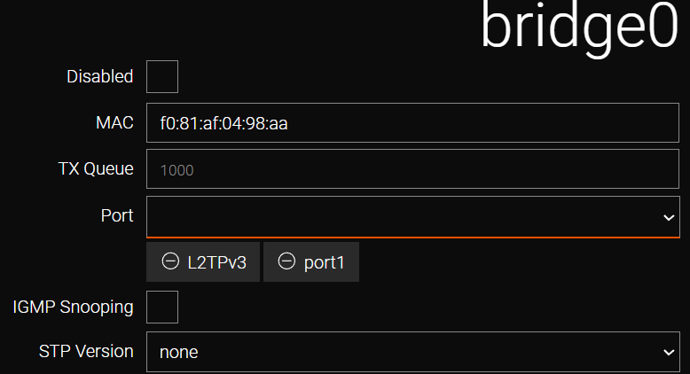
CLI Configuration
-
Use the /ip interface status command to display the list of existing bridges and their parameters.
-
Identify the bridge interface assigned the required IP address and subnet (e.g., 192.168.12.1/24). In this example, the target is bridge0.
/ip interface status -
Navigate to the bridge configuration section /network bridge bridge0
-
View the current ports within the bridge using the port command.
-
Add the tunnel interface to the port list. To maintain existing connectivity, the tunnel interface is added to the current list (e.g., port port1,L2TPv3, where L2TPv3 is the name assigned to the tunnel).
-
Execute the apply command to confirm the bridge settings.
/network bridge bridge0 port L2TPv3
apply
An identical configuration procedure must be performed on the second router.
| By default, tunnel interfaces are not filtered by the firewall. If filtering is required, it must be configured in the /firewall/filter section. |
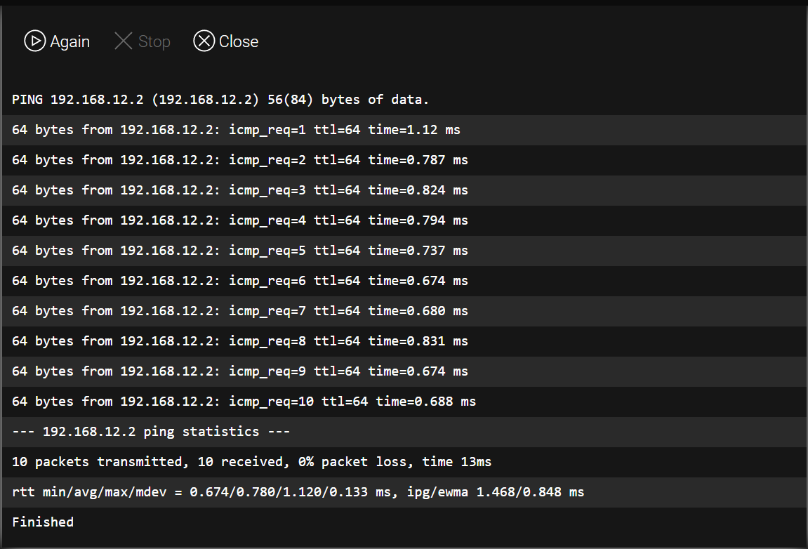
Ping (/tools/ping) — R2 from R1
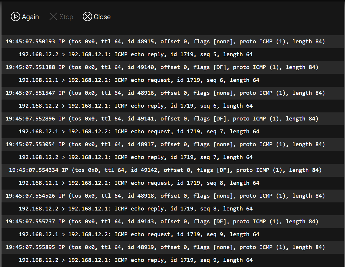
Tunnel operation can be verified by sending a ping from the local address of router R1 to the address of the remote router R2.