SNAT Configuration for Controller Monitoring
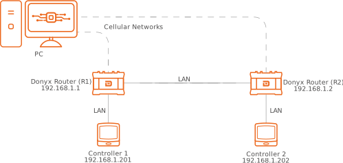
In this scenario, a PC is utilized for monitoring and managing controllers, which are connected to two Donyx routers. The routers are integrated into a single local network.
This topology is implemented for link redundancy and is designed to provide high availability in the event of a connection failure on either channel.
Objective:
To ensure reachability for both controllers through either of the two routers.
Network Redundancy Topology for Controller Monitoring:
Procedure:
To implement this topology, port forwarding rules to each controller must be configured on both routers. Additionally, an SNAT rule must be defined on each device.
Donyx routers support configuration via both the web interface and the CLI.
DNAT (Port Forwarding) Configuration in the Donyx routers Web Interface
Assume that each controller responds to requests on TCP port 80.
In this scenario, port forwarding for R1 must be configured according to the following procedure:
-
Navigate to the /firewall/nat section and click the Add button.
-
In the pop-up panel, select Prerouting from the Chain dropdown list and click OK.

-
In the displayed form, configure port forwarding for the first controller as shown in the example below.
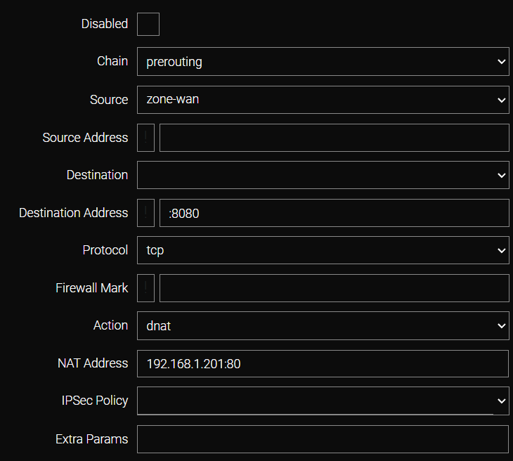
Field |
Value |
Chain |
The Iptables chain where packet processing occurs. For port forwarding (DNAT), the prerouting chain is used. |
Source |
The interface or zone for the processed packets. In this example, zone-wan is used (packets originating from the service provider side). |
Destination Address |
The external port on the ROUTER that will respond to controller requests. For this example, port 8080 is used (notated as :8080). |
Protocol |
The transport protocol (TCP or UDP) utilized by the controller. |
Action |
The action performed on the packet. In this context, dnat (port forwarding). |
NAT Address |
The destination IP address and port to which the traffic is forwarded. |
-
Click Apply to save the settings.
-
Port forwarding for the second controller on R1 is configured in a similar manner, specifying a different external port (8081) and a different destination device address (192.168.1.202). The destination port remains unchanged, as the device responds on that specific port.
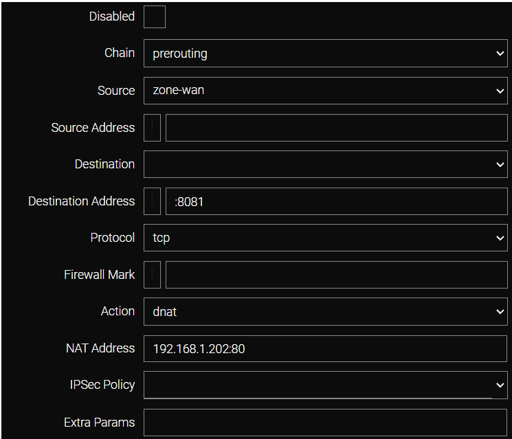
Port forwarding on router R2 is configured identically to the setup on R1.
SNAT Configuration on Donyx Routers
-
Navigate to the /firewall/nat section and click the Add button. In the pop-up panel, select postrouting from the Chain dropdown list and click OK.

-
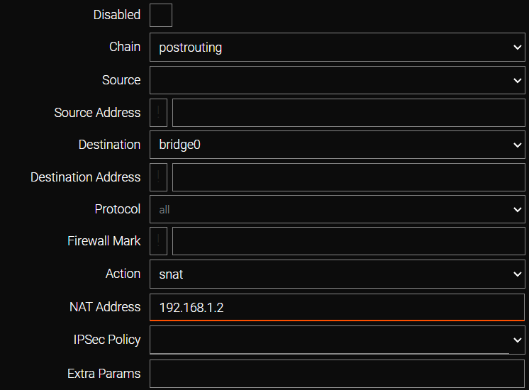
For router R1, complete the form as shown in the example:
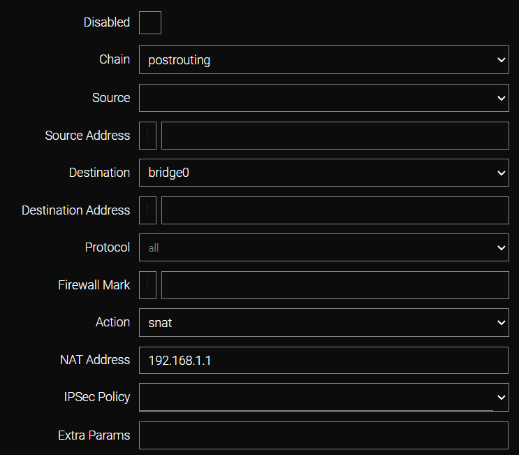
Field |
Value |
Chain |
The Iptables chain where packet processing occurs. For SNAT, the postrouting chain is used. |
Destination |
The interface or zone for the processed packets. In this example, bridge0 (the default network bridge serving the local network) is specified. Ensure that the bridge to which the controller is connected is selected. |
Protocol |
all (default). |
Action |
The action performed on the packet. In this context, snat (source address substitution). |
NAT Address |
The address utilized as the source. In this example, it is 192.168.1.1. |
-
The configuration of router R2 is performed in a similar manner to R1. The primary difference is that 192.168.1.2 is specified as the NAT Address.
-
Click Apply to save the settings.
| All modifications are permanently saved to the router configuration only after executing the /system config commit command or clicking the commit button in the web interface. |
Operational Principles
Controllers #1 and #2 utilize independent Default Routes.
-
For Controller #1 (192.168.1.201), the default gateway is Router R1 (192.168.1.1).
-
For Controller #2 (192.168.1.202), the default gateway is Router R2 (192.168.1.2).
In the absence of an SNAT rule, a packet arriving at the forwarded port of Router R1 for Controller #2 (192.168.1.202) will trigger a response directed to Router R2 (the default gateway). Consequently, the polling PC will not establish a connection with the controller.
When SNAT rules are configured, the source address of the incoming packet is substituted with the router’s own local IP address. Since the local address resides within the same subnet as the controller, the controller directs the response to this known local address rather than following the Default Route.
The response packet returns to the router where the SNAT substitution occurred. The system then performs an inverse address substitution and forwards the packet to the original sender, ensuring established connectivity.
CLI Configuration for Controller Monitoring
Execute the following commands on both Router 1 and Router 2 (commands with a hyphen instead of a parameter value, e.g., disabled -, may be omitted):
For port forwarding to Controller 1
/firewall nat add chain=prerouting
    action dnat
    disabled -
    dst -
    dst-addr :8080
    extra -
    mark -
    nat-addr 192.168.1.201:80
    policy -
    protocol tcp
    src zone-wan
    src-addr -
    apply
For port forwarding to Controller 2
/firewall nat add chain=prerouting
    action dnat
    disabled -
    dst -
    dst-addr :8081
    extra -
    mark -
    nat-addr 192.168.1.202:80
    policy -
    protocol tcp
    src zone-wan
    src-addr -
    apply
For SNAT configuration on R1
/firewall nat add chain=postrouting
    action snat
    disabled -
    dst bridge0
    dst-addr -
    extra -
    mark -
    nat-addr 192.168.1.1
    policy -
    protocol all
    src -
    src-addr -
    apply
For SNAT configuration on R2
/firewall nat add chain=postrouting
    action snat
    disabled -
    dst bridge0
    dst-addr -
    extra -
    mark -
    nat-addr 192.168.1.2
    policy -
    protocol all
    src -
    src-addr -
apply| Configuration is finalized with the command, which writes the settings to the router’s non-volatile memory. |
/system config commit| All modifications are permanently saved to the router configuration only after executing the /system config commit command or clicking the commit button in the web interface. |